THE ANALOG BOARD FOR HEAT
TELESCOPES
The Auger Fluorescence Detector (FD)
is composed by 27 fluorescence telescopes located in four places (Los
Leones, Los Morados, Loma Amarilla and Coihueco) around the perimeter
of the Surface Detector (SD). Each FD site is composed by 6 telescopes,
except Coihueco that consists of 6 + 3 telescopes. The latter
three telescopes have been added to the original FD design at a later
time, they are called High Elevation Auger
Telescopes (HEAT), and have been optimized to extend
the FD
lower limit of detection from 1018
to 1017 eV.
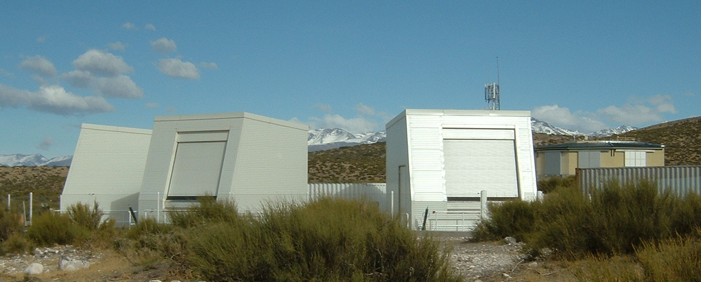
The HEAT telescopes have been built at the distance of about 100 m from the existing FD eye at Coihueco and few meters (about 6 m) below its horizon in three separate shelters gruped together (Figure 1).

At lower energies the emission of fluorescence photons is lower, for this reason low energy showers can be correctly detect only at shorter distances, but at shorter distances they remain in the field of view of each PMT for a shorter time than showers at greater distances, for this reason greater temporal resolution is required. To fulfill this request the front-end electronics design has been optimized with respect to the existing one. In particular, to increase the trigger efficiency the time resolution has been enhanced from 100 ns to 50 ns, therefore the sampling rate of the FADCs placed on the First Level Trigger (FLT) boards has been increased from 10 MHz to 20 MHz. From the point of view of the analog signal conditioning some upgrades have been made and below we will describe the enhancement of the capabilities of the new AB developed .
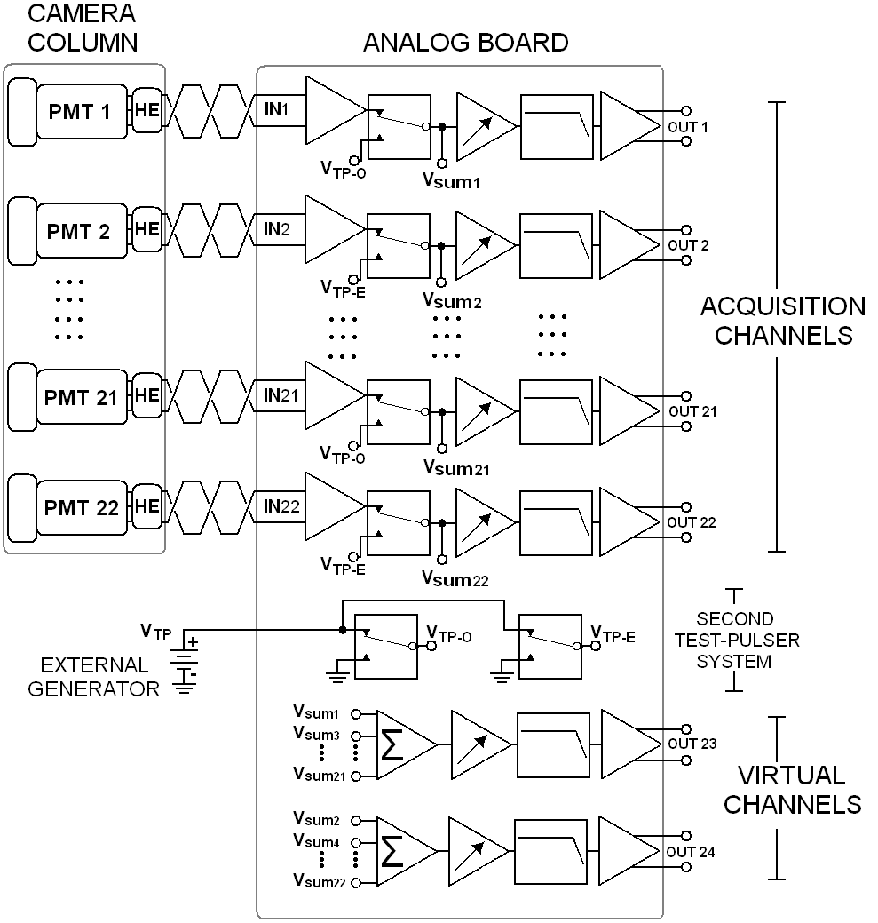
The ABs for HEAT have been designed by the Naples Auger group, and they process the analog signals generated by the PMTs of the camera (the camera is composed by 440 PMTs arranged in a matrix of 22 rows and 20 columns). Each AB (Figure 2) is a multi-channel system composed by 22 + 2 channels: 22 channels receive signals from 22 PMTs of a single camera column, 2 virtual channels allow to recover signals with highest voltage range.

An analog channel (Figure 3) provides signal conditioning for signals generated by one PMT, in particular to:

Figure 3: Block diagram of a single analog channel

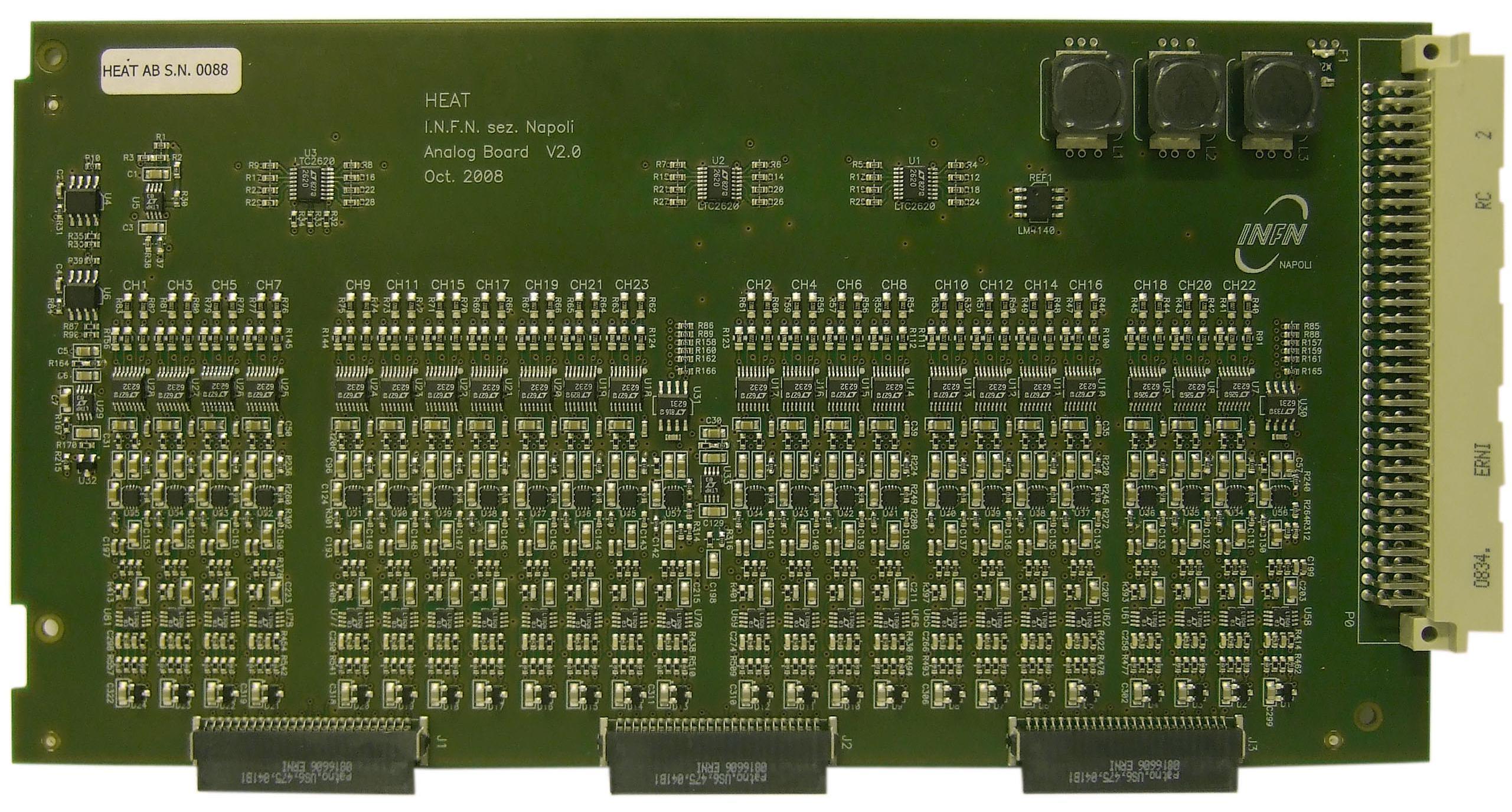
Figure 4: Top view of one of the AB
After the production all the 80 ABs were tested in our laboratory, the main measuraments made to characterize each readout channel of each AB are avaible here: ABs CHARACTERIZATION
The HEAT telescopes have been built at the distance of about 100 m from the existing FD eye at Coihueco and few meters (about 6 m) below its horizon in three separate shelters gruped together (Figure 1).

Figure
1:
The
HEAT telescopes, on the right Coihueco building
At lower energies the emission of fluorescence photons is lower, for this reason low energy showers can be correctly detect only at shorter distances, but at shorter distances they remain in the field of view of each PMT for a shorter time than showers at greater distances, for this reason greater temporal resolution is required. To fulfill this request the front-end electronics design has been optimized with respect to the existing one. In particular, to increase the trigger efficiency the time resolution has been enhanced from 100 ns to 50 ns, therefore the sampling rate of the FADCs placed on the First Level Trigger (FLT) boards has been increased from 10 MHz to 20 MHz. From the point of view of the analog signal conditioning some upgrades have been made and below we will describe the enhancement of the capabilities of the new AB developed .
The ABs for HEAT have been designed by the Naples Auger group, and they process the analog signals generated by the PMTs of the camera (the camera is composed by 440 PMTs arranged in a matrix of 22 rows and 20 columns). Each AB (Figure 2) is a multi-channel system composed by 22 + 2 channels: 22 channels receive signals from 22 PMTs of a single camera column, 2 virtual channels allow to recover signals with highest voltage range.

Figure
2:
Circuit
block
diagram
of
an AB connected to a single camera column
An analog channel (Figure 3) provides signal conditioning for signals generated by one PMT, in particular to:
- amplify the signal in order to reach the voltage level required by the FADC placed on the FLT board;
- increase the signal-to-noise ratio;
- filter
the signal in order to significantly attenuate the
aliasing distortion due to the sampling process performed at 20 MHz.

Figure 3: Block diagram of a single analog channel
- The Input Stage receives signals via twisted pair cable, provides impedance matching and differential to single-ended conversion;
- The Test-Pulser System allows injection of pulses with programmable width and amplitude in order to check the whole acquisition chain;
- The Variable Gain Amplifier (VGA) is used to balance the gain spread of the PMTs, and its total gain can change in steps of 0.006 dB from 12 dB to 36 dB;
- The Anti-Aliasing Filter is a 5-pole Bessel low-pass filter, and its purpose is to significantly attenuate the aliasing distortion due to the sampling proces performed by the FADC placed on the FLT board;
- The Output Stage
drives the differential FADC placed on the FLT board.

Figure 4: Top view of one of the AB
After the production all the 80 ABs were tested in our laboratory, the main measuraments made to characterize each readout channel of each AB are avaible here: ABs CHARACTERIZATION